Showing posts with label retro. Show all posts

Monday, March 30, 2020

ZX80 Replica

I always had a soft spot for the original ZX-80 computer. Never owned one since it was too expensive for me when it was released, and now I got the money it is still too expensive. Even though almost 50000 units were made, lots of them were lost over the years due to the bad build-quality. So €200-€500,- on eBay is not uncommon for a unit in good condition. 
The original ZX80
When I started building my first 3D printer it was always in the back of my head that it could be used for creating a ZX-80 replica. That did not really work out, since it was too inaccurate and the effective build plate was just too small. 
But my new printer has a build plate of 210x210 and it prints significantly better, so now is the time to build my own ZX-80.
Fortunately, thanks to the current retro computing revival, there are a lot of resources.First there is the ZX80 replacement keyboard on Sell My Retro. This is an excellent keyboard, with actual tactile switches, which makes it much easier to type on than the original. Also available:
original rivets, again on Sell my Retro.
And the design files are on Thingiverse. These were not exactly to my liking, so I made quite some changes. Mainly to make them easier to print, and to make sure that the new keyboard would fit.

There are a lot of images available, but most are just showing the complete computer from the front or side. There are lots of images on this site that also show the rear, bottom and inside. I used these to refine my 3D design, which is now available on Thingiverse.

And if you don't want or cannot print the case yourself, it is also available as a complete printed part on Shapeways. It's not cheap (about € 140,- for the set) but it obviously has a smoother finish and the bottom part is in one piece.

First part : the top cover. 

It took 27.3 hours to print, but turned out really nice. Unfortunately  there was some warping on the edges, but not too bad and I can probably correct this by heating it a little. And 4 solid layers for the top was not enough to completely hide the support structure, so the honeycomb pattern is still vaguely visible on the surface.

Part two : the bottom section.

Since I could not print the whole bottom section on my printer I had to split it into two parts. By adding some support and making some minor changes to the basic shapes, I ended up with two printable pieces that can be bolted and glued together.

The electronics

The internals are based on a Raspberry Pi Zero W. This is nice and small, and has enough power to emulate a ZX80. Since I wanted to make it close to the original I decided the rear connections had to be the same as on the original unit. 

Three 3.5 mm jack sockets, an RCA jack and the board edge connector. The manual shows what is connected where:

If we just apply 5V to the power jack we can connect that straight to the RPi (pin  2,4 and 6 on the header). The RCA jack can be connected to the TV out connection :


 The keyboard

 The ZX 80 or ZX81 keyboard is a simple matrix-keyboard. 
Original keyboard schematic


It is actually 2 matrices of 4 x 5 each, and we will need 5+8 = 13 I/O pins to read it. Most people use an Arduino to read the matrix and emulate a standard USB keyboard. And I actually went the same route when converting a C64 to USB keyboard. Since space in the ZX80 case is limited it would be nice to read the keyboard straight into the Pi. The Pi has 27 GPIO pins so that should be enough. Unfortunately the GPIO pins are spread almost at random over the connector, and some pins are better not used (like 0 and 1). But since we can just map IO pins in software this is not so relevant and I just connected both keyboard cables to all GPIOs on the left side (1..39)

Numbering scheme:
KB1      5 ,4 ,3 ,2 ,1  KB2 6,4,2,1 ,3 ,5 ,7 ,9
GPIO     19,13,6 ,5 ,11     2,3,4,17,27,22,10,9
WiringPi 24,23,22,21,14     8,9,7,0 ,2 ,3 ,12,13


Note that I also mounted the 8 diodes in the KB2 lines, but I mounted them the other way around as compared to the original schematic.Basically this does not matter, it just inverts the logic as used in the software to read the pins. As I had already written the software before I notice that the diodes were reversed I decided to leave it that way.


To keep the PCB in place I simply bolted it to a small piece of wood that I taped to the bottom using some double sided tape.

Software

Reading the keyboard

Controlling the IOpins on an RPi is easiest using the wiringPi library, which is already installed on Raspbian. Check if this is really the case by typing 'gpio -v' on the command-line. If it is there it will return the copyright and version info. Typing 'gpio - readall' will give the pin-mapping from the GPIO to WiringPi pin numbers.

Since I'm not the first one to read a matrix keyboard, I quickly found a Python project that does exactly what I wanted. This was created by Mr PJ Evans, and he did exactly what I'm trying to do now, only for a Spectrum.The Python code was not hard to translate to C.
I added one special combined key command to force a soft reset:

SHIFT + '1'  + SPACE  :Reset the ZX80(soft reset)

The Emulator

There are plenty ZX80 / 81 emulators available, but I needed one that was written in C, open source, and not too complex so I could inject my own keyboard reading code. I looked at Zesarux, which is a great emulator that supports teh full range of Sinclair computers. This however also makes it quite a massive project. And most of the naming and comments are in Spanish, which makes a bit hard for me to find my way around. 
So I opted for the SZ81 project. Since this is just for emulating the ZX80 and ZX81 it is much smaller. I assumed it was just a matter of finding where the keyboard is read, and add my own function to read it from the hardware keyboard. Which is partially true: I could get it to work for entering basic commands and running it. But as soon as the emulator switches to 'special' modes like loading or saving a file the program uses all kind of tricks to send virtual  keyboard, joystick and mouse commands. And these always seem to conflict with the keys as pressed on the keyboard so after several days I just gave up on this one too.
So I went one step back, to the original xz81 emulator which SZ81 was based on. This uses standard X-Windows, and is pretty basic :http://www.svgalib.org/rus/z81.html. It's already an old project, and the source code is only available as a .ZIP file. 

My version, with the keyboard reading routine, is available on GitHub.Note that I included the ZX80.rom and ZX81.rom file. This may be somewhat illegal, as mentioned by most emulator projects, but since they are that easy to find at multiple places I thought it would be rather odd not to include them.
You can check out the project using the following command:

git clone https://github.com/Cees-Meijer/ZX81-RPi.git

Before compiling it, make sure you have installed the X11 development libraries:

sudo apt-get install libx11-dev           // for X11/Xlib.h
sudo apt-get install libxt-dev
sudo apt-get install libxtst-dev 

It is set to compile for ZX80, but if you want the ZX81 version you can change the line:
int zx80=1;  in 'common.c' to int zx80=0;

The scaling is set to 2 in the Makefile:

XDEF=-DSCALE=2 -DMITSHM

This is the right setting for using the composite video output. When using the standard HDMI output this can be set to 3 or maybe even 4.

Build the software:
sudo make xz81
Install everything to the right position:
sudo make install
Make sure the ZX80.rom and / or the ZX81.ROM file are in '/usr/local/lib/z81/'. (This should be taken care of by the 'sudo make install' ).

Setting up the Pi

When the emulator starts it will take a while to boot and show all the Raspbian images and start screen, which does not add to the retro feeling. So I first considered using the pipaOS distro, which is also used by  'Obsolescence Guaranteed' for the PiPDP-8. This is very lightweight and boots really fast. But in the end I did have to install XWin, GCC and GIT anyway, so it's probably simpler to start with the standard Raspbian Lite.

First use raspi-config to enable SSH, so you can use FileZilla to transfer files to the system. (Interfacing Options->SSH). By doing this first you make sure that if something goes wrong, and you get stuck in the emulator, you can still access the Pi.
Next go to boot options, and make sure it boots automatically using the 'Console Autologin' option.


Under 'Advanced settings', disable screen blanking ! This is very important, or else the screen will go blank after 10 minutes, and since there is no 'real' keyboard attached it will not come back again if you press a key on the ZX80 keyboard.

To start the emulator automatically on startup, edit the rc.local file:

 sudo nano /etc/rc.local 

Add the line:
 sudo xinit /home/pi/projects/ZX81-RPi/xz81 &

Right before the 'exit 0'. (Don't forget the ampersand '&'  on the end)

If this works, you can follow the instructions on how to remove all Raspbian boot images and texts.

We can speed up the boot time by adding the following lines to boot/config.txt:

 # Disable bluetooth 
 dtoverlay=pi3-disable-bt
 # Set the bootloader delay to 0 seconds. 
 boot_delay=0

Also in config.txt are the settings for the video output. To make sure the composite video output works, check these two lines:

#uncomment to force a a HDMI mode rather than DVI
 #hdmi_drive=2

#uncomment for composite PAL
 sdtv_mode=2

(or any of the other 5 available video modes)
Note that though 'hdmi_drive' is commented out, the Pi will likely still boot on HDMI if a HDMI monitor is connected.


Finishing touch: the stickers

After some research I found that the size of the 'sinclair ZX80' logo is 27 x 70 mm. That was enough to scale the image that I already found somewhere and so create some really nice stickers. 


The .pdf is available here. When printed on glossy sticker sheets they look really good.

Zesarux

Currently ZEsaRUX is one of the best ZX type emulators. As mentioned, I have looked into this one but decided not to use it for my project. For reference I do include some suggestions on how to compile and use it.
The program is only available as source code, but there are instructions on how to build it on the Raspberry Pi as well.

When running Raspbian Lite from the command line, we will have to start from there.
First : Install GIT
$ sudo apt-get install git
Next install SDL
$ sudo apt-get install libsdl1.2-dev
Now I created a folder zesarux in my ./Projects folder and cloned it as follows:
$ sudo git clone https://github.com/chernandezba/zesarux.git
This does require that you have a GitHub account yourself, as it could ask you for your username and password !

cd /usr/src/zesarux/zesarux/src 
We must be in the src directory of the zesarux project


 $ export CFLAGS=-O2
 $ export LDFLAGS=-O2


 $ sudo ./configure --enable-raspberry


If this command executes successfully it will create the make file.

    $ sudo make clean
    $ sudo make

The 'make' command will start the compiling. This will take a while. On the Rpi Zero it took about 3 minutes.
According to the docs, The recommended way to start the emulator is using the following settings:
--disableborder --zoom 1 --fullscreen --vo fbdev --ao sdl --no-detect-realvideo

$ ./zesarux  --disableborder --zoom 1 --fullscreen --vo fbdev --ao sdl --no-detect-realvideo
And yes, this works! after selecting the ZX80 in the menu we get a very realistic ZX80 screen.


It doesn't always work as expected. When starting it from a system with full Raspbian I got the emulator just in the top left corner, and had to add --zoom=4 to get to fullscreen.
Since I wanted it to start as ZX80, I also added the --machine ZX80 option. 

Sunday, May 01, 2016

Commodore VIC-20


The famous VIC-20. Predecessor to the Commodore 64, introduced in 1980 and thus being the very first affordable (US$300,-) colour computer.  Almost three million units were sold at the time, so they are still not very rare.
The unit I got (for €40,-) is in pretty good condition. The case has some inevitable yellow marks, caused by the reaction of UV light with the flame-retardand in the plastic. Something that could be removed (just google for 'RetrOBright')  but I think I'll just leave it like it is and not risk damaging the plastic.
The unit came without any cables, so the first step will be to find out how to connect the monitor. As always, this information is easy to be found. I found a complete overview on Retro Isle this time.
The video is on the 5-pin DIN plug, 2 = GND, 4= Video. 

Unfortunately it does not seem to work.
My small LCD monitor (that works fine with my TRS-80 and Acorn Electron) says 'no signal'. When measuring the video signal on the outside and on the board itself using an oscilloscope it looks good. But even adjusting the output level to the max does not solve the issue.
Just to be sure there is something wrong with it I connected it to the flatscreen television in the living room, only to find that it actually does work....
Looking into this issue I found several references to the fact that the video signal of the VIC is really bad, which did not really matter in those days since the standard television and monitor was pretty tolerant, but is a problem for our modern, all digital, LCD screens.
On the 'Denial WIKI' there are a few suggestions on how to improve video output which might be worth trying.


Monday, April 25, 2016

Acorn Electron

For only €20,- I purchased an Acorn Electron in excellent condition. The Electron was developed around 1982 as a direct competitor to the the Sinclair Spectrum, and even though it had some drawbacks it was sold in such large quantities that it is not to rare today. No need to tell the history, since there is already an excellent article on The Register about that.
Although this machine was not really on  my wish-list it's a pleasant surprise. First it's very compact and well-built. The housing is made of solid plastic, which even after 30 years does not show any colouring or scratches.
The keyboard is pretty good, and although most keys have multiple functions they are not crammed with it like the Commodore 64 or Sinclair spectrum.
The inside looks equally good. Just four screws have to be taken out to reveal a very clean motherboard and separate power supply .
  
They were very serious about the shielding against electromagnetic radiation, as clearly visible on the keyboard side.  

The user guide is excellent. It starts (as many user guides from this era) with an explanation of what a computer is: 

"A computer is a general purpose electronic machine that can be instructed to do a great variety of things - play games, perform complex calculations, store and retrieve information, display graphs and so on."
(You can read the whole guide on Acorn Electron World .  )

What surprised me is the possibilities of the Basic interpreter. It actually has named functions and procedures, a 'repeat..until' loop, quite advanced graphic functions and a built-in assembler to write machine code. And this machine code is definitely worth checking out, because the Basic is not really fast...

Enabling Colour on the composite video output

After working with it for while having it connected to a LCD monitor I noticed that it did not display colour. Initially worried that maybe the video circuit was damaged, I soon found out that this is intentional. The standard composite video output is set to black and white, but there is a link on the board that can be made to enable the colour signal. 
It's marked 'LK4', and I just soldered a link on it. After that the monitor shows colour as expected, but I do have the impression that the letters are less crisp (which was probably the reason for Acorn to have just black and white as a default)

Loading software

The machine came without a cassette recorder, but it should work with any standard audio recorder. Which in these days can be replaced by simple recording / replay software on a PC. I used Audacity to record a simple Basic program, and after fiddling a bit with the audio levels (for recording as well as playback) it worked fine.
Loading standard software appeared a bit harder. Almost all software published for the Electron is available online, usually in the '.UEF' ('Universal Emulator Format') file format. A very simple Windows program named FreeUEF can be used to either replay it as audio or to convert it to a  .WAV file that can be replayed by other software. The last solution did not really work for me. Replaying the created .WAV files using Audacity always gave an error after reading the first block. All other blocks seem to load fine, but the program will not run on the Electron.

Finally I used an Android App on my tablet named 'TapDancer'. This works flawlessly and because it actually looks like a Commodore Datasette it adds a little extra to the retro-feeling...

And if you want to go a step further, there is the GoSDC  expansion module that lets you load programs from an SD card. But let's face it: compared to loading programs using the tape interface it only saves you a minute during the loading itself. So unless you switch programs every 5 minutes I doubt if this is really worth it.


Tuesday, November 03, 2015

Go for C64 - Part II - The Arduino Leonardo solution

After trying to turn my C64  into a USB keyboard the whole project ended in a cupboard for a year at 90% completion. In the end the whole PICAXE - Arduino Pro Micro combination felt a bit clumsy.
Then I recently stumbled on a blogpost where someone connects a ZX81 keyboard to the Arduino Leonardo, and I found a cheap (€12,-) Leonardo-clone so I decided this was the way to go.

The board came with front headers, which makes connecting the keyboard super easy.
This is the C64 Keyboard matrix: ( diagram from the 'WaitingForFriday' blog)


Corrected C64 Keyboard matrix and keyboard connector diagrams
It is connected to the Arduino as follows:

A - D0
B - D1
C - D2
D - D3
E - D4
F - D5
G - D6
H - D7
0 - D8
1 - D9
2 - D10
3 - D11
4 - A0
5 - A1
6 - A2
7 - A3

The code can be a mix of the code from 'Biosrythm' and TechTonic . :

#include <Keyboard.h>

// ZX81 USB Keyboard for Leonardo
// (c) Dave Curran
// 2013-04-27

// Modified with Function keys by Tony Smith
// 2014-02-15
// Adapted for use with Commodore 64 Keyboard by Cees Meijer
// 2015-11-04
// Enable the debug mode (serial output) by keeping F7 pressed when 
// starting the program
// Special Commodore graphic characters are not implemented

#define NUM_ROWS 8
#define NUM_COLS 8

#define SHIFT_ROW 3
#define SHIFT_COL 1

#define RSHIFT_ROW 4
#define RSHIFT_COL 6

#define F7_ROW 7
#define F7_COL 7

#define DEBOUNCE_VALUE 100
#define REPEAT_DELAY 500

// Keymap for normal use

byte keyMap[NUM_ROWS][NUM_COLS] =
{
  {'1', '3', '5', '7', '9', '+', '$', KEY_BACKSPACE},
  {KEY_LEFT_ARROW, 'w', 'r', 'y', 'i', 'p', '*', KEY_RETURN},
  {'~', 'a', 'd', 'g', 'j', 'l', ';', KEY_LEFT_ARROW},
  {'~', 0  , 'x', 'v', 'n', ',', '/', KEY_UP_ARROW},
  {' ', 'z', 'c', 'b', 'm', '.', 0  , KEY_F1},
  {'~', 's', 'f', 'h', 'k',':', '=' , KEY_F3},
  {'q', 'e', 't', 'u', 'o', '@', KEY_UP_ARROW, KEY_F5},
  {'2', '4', '6', '8', '0', '-', '~', KEY_F7}
};

// Keymap if Shift is pressed

byte keyMapShifted[NUM_ROWS][NUM_COLS] =
{
  {'!', '#', '%', '\'', ')', '+', '$', KEY_BACKSPACE},
  {KEY_LEFT_ARROW, 'W', 'R', 'Y', 'I', 'P', '*', KEY_RETURN},
  {'~', 'A', 'D', 'G', 'J', 'L', ']', KEY_RIGHT_ARROW},
  {'~', 0  , 'X', 'V', 'N', '<', '?', KEY_DOWN_ARROW},
  {' ', 'Z', 'C', 'B', 'M', '>', 0  ,KEY_F2},
  {'~', 'S', 'F', 'H', 'K','[', '=', KEY_F4},
  {'Q', 'E', 'T', 'U', 'O', '@', KEY_UP_ARROW, KEY_F6},
  {'"', '$', '&', '(', '0', '-', '~', KEY_F8}
};
// Global Variables

int debounceCount[NUM_ROWS][NUM_COLS];
int altKeyFlag;
bool serial_output;

// Define the row and column pins

byte colPins[NUM_COLS] = {0,1,2 ,3 ,4 ,5 ,6 ,7}; // A,B,C,D,E,F,G,H
byte rowPins[NUM_ROWS] = {8,9,10,11,A0,A1,A2,A3};

// SETUP

void setup()
{
  // Set all pins as inputs and activate pull-ups
  serial_output = false;
  for (byte c = 0 ; c < NUM_COLS ; c++)
  {
    pinMode(colPins[c], INPUT);
    digitalWrite(colPins[c], HIGH);
    
    // Clear debounce counts
    
    for (byte r = 0 ; r < NUM_ROWS ; r++)
    {
      debounceCount[r][c] = 0;
    }
  }
  
  // Set all pins as inputs
  
  for (byte r = 0 ; r < NUM_ROWS ; r++)
  {
    pinMode(rowPins[r], INPUT);
  }
  
  // Function key is NOT pressed
  
  altKeyFlag = ALT_KEY_OFF;
  pinMode(rowPins[F7_ROW], OUTPUT);
  if (digitalRead(colPins[F7_COL]) == LOW) serial_output = true;
  // Initialise the keyboard
  if (serial_output )
   {
    Serial.begin(9600);
   }
   else
   {
    Keyboard.begin();  
   }
}

// LOOP

void loop()
{
  bool shifted = false;
  bool r_shifted = false;
  bool keyPressed = false;
  
  // Check for the Shift key being pressed
  
  pinMode(rowPins[SHIFT_ROW], OUTPUT);
  if (digitalRead(colPins[SHIFT_COL]) == LOW) shifted = true;
  
  pinMode(rowPins[RSHIFT_ROW], OUTPUT);
  if (digitalRead(colPins[RSHIFT_COL]) == LOW) shifted = true;
  
    pinMode(rowPins[SHIFT_ROW], INPUT);
    pinMode(rowPins[RSHIFT_ROW], INPUT);
    
    for (byte r = 0 ; r < NUM_ROWS ; r++)
    {
      // Run through the rows, turn them on
      
      pinMode(rowPins[r], OUTPUT);
      digitalWrite(rowPins[r], LOW);
      
      for (byte c = 0 ; c < NUM_COLS ; c++)
      { 
        if (digitalRead(colPins[c]) == LOW)
        {
          // Increase the debounce count
          
          debounceCount[r][c]++;
          
          // Has the switch been pressed continually for long enough?
          
          int count = debounceCount[r][c];
          if (count == DEBOUNCE_VALUE)
          {
            // First press
            
            keyPressed = true;
            pressKey(r, c, shifted);
          }
          else if (count > DEBOUNCE_VALUE)
          {
            // Check for repeats
            
            count -= DEBOUNCE_VALUE;
            if (count % REPEAT_DELAY == 0)
            {
              // Send repeat
              
              keyPressed = true;
              pressKey(r, c, shifted);
            }
          }
        }
        else
        {
          // Not pressed; reset debounce count
          
          debounceCount[r][c] = 0;
        }
      }
     
    // Turn the row back off
     
    pinMode(rowPins[r], INPUT);
    }
    digitalWrite(rowPins[RSHIFT_ROW], LOW);
    digitalWrite(rowPins[SHIFT_ROW], LOW);
  
}

void pressKey(byte r, byte c, bool shifted)
{  
  // Send the keypress
  if (serial_output) 
    { 
    Serial.print("|");Serial.print("\r\n");Serial.print("|"); 
    Serial.print(r);Serial.print(",");Serial.print(c);Serial.print(":");
    }
  byte key = shifted ? keyMapShifted[r][c] : keyMap[r][c];

  if (serial_output)
   {
   if (key > 0){ Serial.write(key);}
   }
   else
   {
   if (key > 0 ) Keyboard.write(key);
   }
  
}


Saturday, October 11, 2014

Go for....C64

My first computer was a TRS-80 Model I. I still have fond memories of this black and grey box with it's black and white screen, 128x48 monochrome graphics, 12" monitor and tape drive for data storage. Unfortunately we sold it when we got the twice as fast and portable Aster CT-80 (4 Mhz clock, two floppy drives!). Only for sentimental reasons I'd love to own one now., but  they are quite rare and therefore relatively expensive on eBay...
Anyway, I always kept a weak spot for these all-in one keyboard computers like the TSR-80, Atari 2600, VIC-20 and of course the Commodore C64. According to Wikipedia 12 to 17 million of these units were sold at the time making this a lot less rare.
 (An uncertainty of 5 Million ? That's so weird there are even special pages dedicated to this mystery..)

Anyway, 12 million or more seems to be enough to saturate the demand even 30 years later and complete systems can be bought for 50 to 100 Euro's. Actually I own a complete system myself. It's a complete, working set including an original tape recorder and diskette drive. I might have to wipe the dust off and find a suitable TV-set to check if it's still 100%. In the meantime I thought it was a nice idea to have just an empty C64 housing with keyboard and use that as a keyboard for my PC. Or maybe mount a Raspberry Pi inside to turn it into a working Linux computer. Or connect it to a tablet running a C64 emulator like C64.EMU .

[ As usual, I'm not the first to think about this and there is even a complete interface for sale: the Keyrah V2. Better (or worse..) there is even an Etsy shop that has Commodore and many other computers converted to USB keyboards. But that's what I consider cheating. At least some hacking has to be done or it would be too easy ! My first thought was to use the Arduino Micro. While building my MAME cabinet I already discovered that this would have been the easiest way to implement a virtual USB keyboard.  On the biosrythm blog there is already a complete description on how to use Arduino to get the C64 keyboard to USB, but he is using the Duemilanove . ]

I picked up an empty C64 from ebay.de for €30 and bought a Arduino Pro Micro for only €7,- (who said hobbies have to be expensive?)

 The cable that sticks out on the right is the keyboard connector that used to be connected to the C64 motherboard.
First we obviously have to find out how the keyboard is actually wired. I found a neat diagram on the 'WaitingForFriday' blog:

Corrected C64 Keyboard matrix and keyboard connector diagrams  
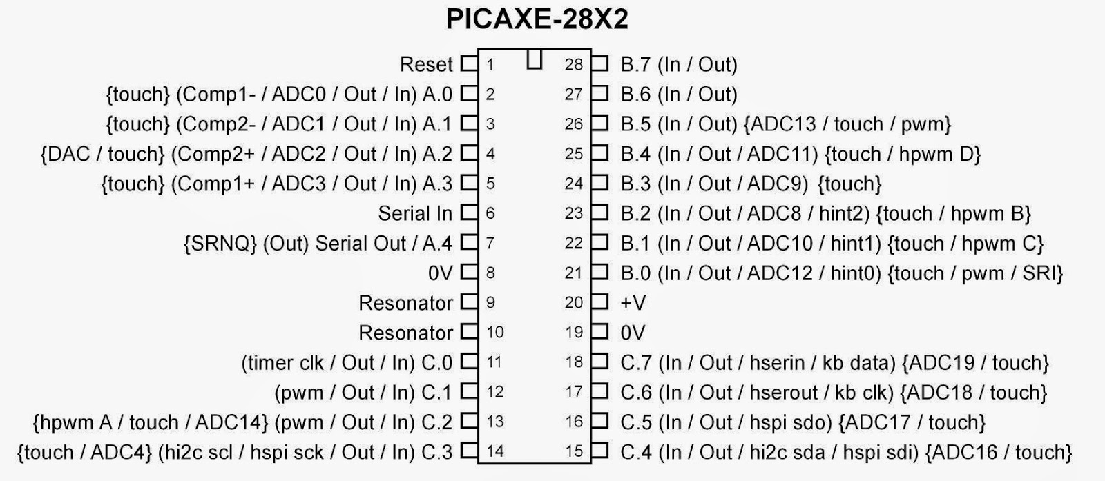
Great, but it presents and unexpected surprise: we will need 16 Input / Outputs for reading this matrix. And the Micro Pro only has 9 digital I/O pins. My first idea was to expand the number of I/O pins by using some shift registers but then I remembered I also had some PICAXE chips in my toolbox. The PICAXE is a standard PIC micro-controller, pre-programmed with a Basic interpreter which makes programming real simple.And the PICAXE 28X2 has 16 freely configurable I/O pins so that should work fine.

This chip even has all the I/O pins nicely laid out,making it easy to route the connector to the chip.
Some soldering will be necessary though to split out the connector in sections that will go to B0..B7
C0...C3 and C4...C7.
 Unfortunately this does not work. The PICAXE does not have any pull up or down resistors on its pins, so when no key is pressed they are all floating which results in random values.Adding a 10K pull up resistor to each input solves this problem immediately.
It's still a lot of puzzling to detect the right keys, certainly in combination with the  left-shift, right-shift or Commodore key but you can find a complete working version of the PICAXE software at the end of this page.
But since the PICAXE lacks an USB output we still need the  Arduino Pro Micro to create a keyboard compatible output.
So the whole exercise has been a fun and useful learning experience, but in hindsight it would have been easier to use the Arduino Leonardo... After all, this is a Pro Micro, but with plenty I/O to implement everything on a single board.


'Commodore 64 Keyboard Decoder. Columns (A..H) connected to Port B. Rows (1..8) to port C
'Both ports have 10K Pull up resistor on each pin


main:
symbol ROWS = b1
symbol COLUMNS = b2
symbol ROW = b4
symbol COLUMN = b5
symbol KEY =b6
symbol CHECK_ROW = b11
symbol CHECK_COL = b12
symbol TEMP_SUB = b13
symbol TEMP_SUB1= b14
symbol SPECIAL_KEY_PRESSED = b15
symbol RIGHT_SHIFT = b16
symbol LEFT_SHIFT = b17
symbol CTRL =b18
symbol PREVIOUS_KEY =b19
symbol KEY_COUNT=b20
symbol KEY_DELAY = b21

PREVIOUS_KEY = 0
KEY_DELAY = 100
do            ; Endless loop
 let dirsC = %11111111 ' switch all pins to outputs
 let dirsB = %00000000 ' switch all pins to inputs
 let pinsC = %00000000 ' switch all outputs low 
 b1 = pinsB 
 let dirsC = %00000000 ' switch all pins to inputs
 let dirsB = %11111111 ' switch all pins to outputs
 let pinsB = %00000000 ' switch all outputs low 
 b2 = pinsC
 
 b3 = NOT b1
 ROWS = NOT b2
 COLUMNS=b3

 'sertxd("B1,B2: ",#b1," ",#b2,13,10)
'Check if Left Shift is pressed 
 CHECK_ROW = %00001000
 CHECK_COL = %00000010 
 gosub CheckRowCol
LEFT_SHIFT = SPECIAL_KEY_PRESSED 
'Check if Right Shift is pressed
 CHECK_ROW = %00010000
 CHECK_COL = %01000000 
 gosub CheckRowCol
RIGHT_SHIFT = SPECIAL_KEY_PRESSED 
'Check if Right Shift is pressed
 CHECK_ROW = %00000100
 CHECK_COL = %00000001 
 gosub CheckRowCol
CTRL = SPECIAL_KEY_PRESSED   


 ROW = ncd ROWS
 COLUMN = ncd COLUMNS
 'sertxd("B1,B2,ROW,COL: ",#b1," ",#b2," ",#ROW," ",#COLUMN,13,10)
if ROW=0 or  COLUMN=0 then goto reset_keycount
 ROW = ROW-1
 COLUMN = COLUMN -1
 b0 = 8*COLUMN + ROW
 if LEFT_SHIFT =1 OR RIGHT_SHIFT=1 then goto Shift_pressed
 
  lookup b0,("1",8,"cr cq23wa~zse45rdxcft67ygvbhu89ijnmko0+pl,.:@-$*;/~=???",13,"?ffff"),KEY
 goto Key_Pressed
 Shift_pressed: 
       lookup b0,("!",8,"cr CQ",34,"#WA~ZSE$%RDXCFT&'YGVBHU()IJNMKO0+PL<>[@-$*]?~=???",13,"?ffff"),KEY
 Key_Pressed:
 'sertxd("KEY PRESSED!",#ROW," ",#COLUMN," ",#b0,":",b1,13,10)
 if KEY = "~" then goto continue     '~ marks an unprintable character (Only Shift is pressed)
 if KEY = PREVIOUS_KEY AND KEY_COUNT < KEY_DELAY then goto count_keys
 if KEY_COUNT <> KEY_DELAY then goto normal_delay
  KEY_DELAY = 3
      normal_delay:
 KEY_COUNT =0
 sertxd(KEY)
 serout A.0,T9600_8,(KEY)
 PREVIOUS_KEY = KEY
 goto continue


count_keys:
 KEY_COUNT = KEY_COUNT+1
 goto continue
reset_keycount:
 KEY_COUNT=0
 KEY=0
 PREVIOUS_KEY =0
 KEY_DELAY = 30
  
continue: 

loop   ; next loop

CheckRowCol:
SPECIAL_KEY_PRESSED = 0
 TEMP_SUB = ROWS and CHECK_ROW       'Check if a specific bit in ROWS is set
 if  TEMP_SUB = 0 then goto NotPressed
 TEMP_SUB = COLUMNS and CHECK_COL    'Check if a specific bit in COLUMNS is set
 if TEMP_SUB = 0 then goto NotPressed
 TEMP_SUB = NOB ROWS                    'Bit in ROWS and in COLUMNS found. Check how many bits in ROWS are set
 if TEMP_SUB = 1 then goto no_bit_reset 'If it is just one bit, do not reset it
 TEMP_SUB = NOT CHECK_ROW          'Invert all bits in the CHECK_ROW
 ROWS = ROWS and TEMP_SUB               'AND it with the ROWS to reset the bit we just found 
 no_bit_reset:
 TEMP_SUB = NOB b2
 if TEMP_SUB = 1 then goto no_bit_reset_2 
 TEMP_SUB= NOT CHECK_COL  
 COLUMNS = COLUMNS and TEMP_SUB 
 no_bit_reset_2:  
 SPECIAL_KEY_PRESSED = 1
NotPressed:
 
return