Monday, March 30, 2020

ZX80 Replica

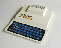
I always had a soft spot for the original ZX-80 computer. Never owned one since it was too expensive for me when it was released, and now I got the money it is still too expensive. Even though almost 50000 units were made, lots of them were lost over the years due to the bad build-quality. So €200-€500,- on eBay is not uncommon for a unit in good condition. 
The original ZX80
When I started building my first 3D printer it was always in the back of my head that it could be used for creating a ZX-80 replica. That did not really work out, since it was too inaccurate and the effective build plate was just too small. 
But my new printer has a build plate of 210x210 and it prints significantly better, so now is the time to build my own ZX-80.
Fortunately, thanks to the current retro computing revival, there are a lot of resources.First there is the ZX80 replacement keyboard on Sell My Retro. This is an excellent keyboard, with actual tactile switches, which makes it much easier to type on than the original. Also available:
original rivets, again on Sell my Retro.
And the design files are on Thingiverse. These were not exactly to my liking, so I made quite some changes. Mainly to make them easier to print, and to make sure that the new keyboard would fit.

There are a lot of images available, but most are just showing the complete computer from the front or side. There are lots of images on this site that also show the rear, bottom and inside. I used these to refine my 3D design, which is now available on Thingiverse.

And if you don't want or cannot print the case yourself, it is also available as a complete printed part on Shapeways. It's not cheap (about € 140,- for the set) but it obviously has a smoother finish and the bottom part is in one piece.

First part : the top cover. 

It took 27.3 hours to print, but turned out really nice. Unfortunately  there was some warping on the edges, but not too bad and I can probably correct this by heating it a little. And 4 solid layers for the top was not enough to completely hide the support structure, so the honeycomb pattern is still vaguely visible on the surface.

Part two : the bottom section.

Since I could not print the whole bottom section on my printer I had to split it into two parts. By adding some support and making some minor changes to the basic shapes, I ended up with two printable pieces that can be bolted and glued together.

The electronics

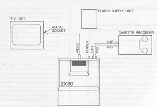
The internals are based on a Raspberry Pi Zero W. This is nice and small, and has enough power to emulate a ZX80. Since I wanted to make it close to the original I decided the rear connections had to be the same as on the original unit. 

Three 3.5 mm jack sockets, an RCA jack and the board edge connector. The manual shows what is connected where:

If we just apply 5V to the power jack we can connect that straight to the RPi (pin  2,4 and 6 on the header). The RCA jack can be connected to the TV out connection :


 The keyboard

 The ZX 80 or ZX81 keyboard is a simple matrix-keyboard. 
Original keyboard schematic


It is actually 2 matrices of 4 x 5 each, and we will need 5+8 = 13 I/O pins to read it. Most people use an Arduino to read the matrix and emulate a standard USB keyboard. And I actually went the same route when converting a C64 to USB keyboard. Since space in the ZX80 case is limited it would be nice to read the keyboard straight into the Pi. The Pi has 27 GPIO pins so that should be enough. Unfortunately the GPIO pins are spread almost at random over the connector, and some pins are better not used (like 0 and 1). But since we can just map IO pins in software this is not so relevant and I just connected both keyboard cables to all GPIOs on the left side (1..39)

Numbering scheme:
KB1      5 ,4 ,3 ,2 ,1  KB2 6,4,2,1 ,3 ,5 ,7 ,9
GPIO     19,13,6 ,5 ,11     2,3,4,17,27,22,10,9
WiringPi 24,23,22,21,14     8,9,7,0 ,2 ,3 ,12,13


Note that I also mounted the 8 diodes in the KB2 lines, but I mounted them the other way around as compared to the original schematic.Basically this does not matter, it just inverts the logic as used in the software to read the pins. As I had already written the software before I notice that the diodes were reversed I decided to leave it that way.


To keep the PCB in place I simply bolted it to a small piece of wood that I taped to the bottom using some double sided tape.

Software

Reading the keyboard

Controlling the IOpins on an RPi is easiest using the wiringPi library, which is already installed on Raspbian. Check if this is really the case by typing 'gpio -v' on the command-line. If it is there it will return the copyright and version info. Typing 'gpio - readall' will give the pin-mapping from the GPIO to WiringPi pin numbers.

Since I'm not the first one to read a matrix keyboard, I quickly found a Python project that does exactly what I wanted. This was created by Mr PJ Evans, and he did exactly what I'm trying to do now, only for a Spectrum.The Python code was not hard to translate to C.
I added one special combined key command to force a soft reset:

SHIFT + '1'  + SPACE  :Reset the ZX80(soft reset)

The Emulator

There are plenty ZX80 / 81 emulators available, but I needed one that was written in C, open source, and not too complex so I could inject my own keyboard reading code. I looked at Zesarux, which is a great emulator that supports teh full range of Sinclair computers. This however also makes it quite a massive project. And most of the naming and comments are in Spanish, which makes a bit hard for me to find my way around. 
So I opted for the SZ81 project. Since this is just for emulating the ZX80 and ZX81 it is much smaller. I assumed it was just a matter of finding where the keyboard is read, and add my own function to read it from the hardware keyboard. Which is partially true: I could get it to work for entering basic commands and running it. But as soon as the emulator switches to 'special' modes like loading or saving a file the program uses all kind of tricks to send virtual  keyboard, joystick and mouse commands. And these always seem to conflict with the keys as pressed on the keyboard so after several days I just gave up on this one too.
So I went one step back, to the original xz81 emulator which SZ81 was based on. This uses standard X-Windows, and is pretty basic :http://www.svgalib.org/rus/z81.html. It's already an old project, and the source code is only available as a .ZIP file. 

My version, with the keyboard reading routine, is available on GitHub.Note that I included the ZX80.rom and ZX81.rom file. This may be somewhat illegal, as mentioned by most emulator projects, but since they are that easy to find at multiple places I thought it would be rather odd not to include them.
You can check out the project using the following command:

git clone https://github.com/Cees-Meijer/ZX81-RPi.git

Before compiling it, make sure you have installed the X11 development libraries:

sudo apt-get install libx11-dev           // for X11/Xlib.h
sudo apt-get install libxt-dev
sudo apt-get install libxtst-dev 

It is set to compile for ZX80, but if you want the ZX81 version you can change the line:
int zx80=1;  in 'common.c' to int zx80=0;

The scaling is set to 2 in the Makefile:

XDEF=-DSCALE=2 -DMITSHM

This is the right setting for using the composite video output. When using the standard HDMI output this can be set to 3 or maybe even 4.

Build the software:
sudo make xz81
Install everything to the right position:
sudo make install
Make sure the ZX80.rom and / or the ZX81.ROM file are in '/usr/local/lib/z81/'. (This should be taken care of by the 'sudo make install' ).

Setting up the Pi

When the emulator starts it will take a while to boot and show all the Raspbian images and start screen, which does not add to the retro feeling. So I first considered using the pipaOS distro, which is also used by  'Obsolescence Guaranteed' for the PiPDP-8. This is very lightweight and boots really fast. But in the end I did have to install XWin, GCC and GIT anyway, so it's probably simpler to start with the standard Raspbian Lite.

First use raspi-config to enable SSH, so you can use FileZilla to transfer files to the system. (Interfacing Options->SSH). By doing this first you make sure that if something goes wrong, and you get stuck in the emulator, you can still access the Pi.
Next go to boot options, and make sure it boots automatically using the 'Console Autologin' option.


Under 'Advanced settings', disable screen blanking ! This is very important, or else the screen will go blank after 10 minutes, and since there is no 'real' keyboard attached it will not come back again if you press a key on the ZX80 keyboard.

To start the emulator automatically on startup, edit the rc.local file:

 sudo nano /etc/rc.local 

Add the line:
 sudo xinit /home/pi/projects/ZX81-RPi/xz81 &

Right before the 'exit 0'. (Don't forget the ampersand '&'  on the end)

If this works, you can follow the instructions on how to remove all Raspbian boot images and texts.

We can speed up the boot time by adding the following lines to boot/config.txt:

 # Disable bluetooth 
 dtoverlay=pi3-disable-bt
 # Set the bootloader delay to 0 seconds. 
 boot_delay=0

Also in config.txt are the settings for the video output. To make sure the composite video output works, check these two lines:

#uncomment to force a a HDMI mode rather than DVI
 #hdmi_drive=2

#uncomment for composite PAL
 sdtv_mode=2

(or any of the other 5 available video modes)
Note that though 'hdmi_drive' is commented out, the Pi will likely still boot on HDMI if a HDMI monitor is connected.


Finishing touch: the stickers

After some research I found that the size of the 'sinclair ZX80' logo is 27 x 70 mm. That was enough to scale the image that I already found somewhere and so create some really nice stickers. 


The .pdf is available here. When printed on glossy sticker sheets they look really good.

Zesarux

Currently ZEsaRUX is one of the best ZX type emulators. As mentioned, I have looked into this one but decided not to use it for my project. For reference I do include some suggestions on how to compile and use it.
The program is only available as source code, but there are instructions on how to build it on the Raspberry Pi as well.

When running Raspbian Lite from the command line, we will have to start from there.
First : Install GIT
$ sudo apt-get install git
Next install SDL
$ sudo apt-get install libsdl1.2-dev
Now I created a folder zesarux in my ./Projects folder and cloned it as follows:
$ sudo git clone https://github.com/chernandezba/zesarux.git
This does require that you have a GitHub account yourself, as it could ask you for your username and password !

cd /usr/src/zesarux/zesarux/src 
We must be in the src directory of the zesarux project


 $ export CFLAGS=-O2
 $ export LDFLAGS=-O2


 $ sudo ./configure --enable-raspberry


If this command executes successfully it will create the make file.

    $ sudo make clean
    $ sudo make

The 'make' command will start the compiling. This will take a while. On the Rpi Zero it took about 3 minutes.
According to the docs, The recommended way to start the emulator is using the following settings:
--disableborder --zoom 1 --fullscreen --vo fbdev --ao sdl --no-detect-realvideo

$ ./zesarux  --disableborder --zoom 1 --fullscreen --vo fbdev --ao sdl --no-detect-realvideo
And yes, this works! after selecting the ZX80 in the menu we get a very realistic ZX80 screen.


It doesn't always work as expected. When starting it from a system with full Raspbian I got the emulator just in the top left corner, and had to add --zoom=4 to get to fullscreen.
Since I wanted it to start as ZX80, I also added the --machine ZX80 option. 

Wednesday, October 23, 2019

The path to LoRaWAN

In 2017 I already tried to get a LoRa based radio link working. Which worked, but only as a
local send / receive solution. At the time The Things Network (TTN) was already operational, but it was quite complex to get started with it, certainly if you don't live near a public TTN node so you could not just send some data to it. I briefly considered setting up my own station, but at an estimated cost of €300,- this was still a bit too much for just a hobby project.
Nowadays TTN has matured, and it is easier to find information on how to access it. There is a complete description on Adafruit on how to build a single channel gateway, and there are several DIY project on how to build simple LoRa Nodes. 
The easiest way would of course be to buy a complete LoRa enabled board, like the LoPy,  the Adafruit Feather with LoRathe WISEN Whisper Node, the MIKRO Electronika Lora5 Click, or just one of the TTN products. (And there are many more, just Google 'LoRa Board')
 
But I already have these Dragino LoRa Bee units and I want to use them. Should not be that hard since they are basically just RF95W transceiver modules on a carrier board. And the RF95 modules are at the heart of 99% of all other LoRa devices. 
A very nice description of a DIY LoRa node is described by Mario Zwiers in a few blog posts that basically describe what I wanted to do. He created a small PCB with an Arduino Micro, a battery charger and a bare RF95W module. Unfortunately he just created the PCB from scratch, without a schematic. So I have to figure that out myself, but since the combinations are limited that cannot be too hard.

Connecting LoRa Bee and Raspberry Pi Zero W

 Pi to LoRa Bee wiring:
  • 3.3V to Raspberry Pi 3.3V
  • GND to Raspberry Pi Ground
  • DIO0 to Raspberry Pi GPIO #3
  • RST to Raspberry Pi GPIO #25
  • SCK to Raspberry Pi SCK
  • MISO to Raspberry Pi MISO
  • MOSI to Raspberry Pi MOSI
  • CS to Raspberry Pi CE1  


Next I followed the basic instructions on installing Python. First installed the latest Raspbian to an SD card. Booted it on the Pi, and used raspi-config to set a Hostname, new password, and the WiFi network parameters. And from the 'Interfacing Options' section I also enabled SSH, SPI and I2C.
Run the standard updates:
sudo apt-get update
sudo apt-get upgrade
and
sudo pip3 install --upgrade setuptools
If above doesn't work try
sudo apt-get install python3-pip

Then install the GPIO libraries:
pip3 install RPI.GPIO

And the Adafruit libraries:
pip3 install adafruit-blinka 


(All this is also on the Adafruit site, I just repeated the steps here for convenience)
Next install the RFM libraries:
sudo pip3 install adafruit-circuitpython-rfm9x

After that I created a simplified version of the Adafruit sample program that would just check if the RFM unit was connected and working. Note that I changed the frequency setting in the RFM9x() function to 868.0, which is the frequency used in Europe.

#Learn Guide: https://learn.adafruit.com/lora-and-lorawan-for-raspberry-pi
#Author: Brent Rubell for Adafruit Industries

import time
import busio
from digitalio import DigitalInOut, Direction, Pull
import board

# Import the RFM9x radio module.
import adafruit_rfm9x


# Configure RFM9x LoRa Radio
CS = DigitalInOut(board.CE1)
RESET = DigitalInOut(board.D25)
spi = busio.SPI(board.SCK, MOSI=board.MOSI, MISO=board.MISO)

    # Attempt to set up the RFM9x Module
try:
    rfm9x = adafruit_rfm9x.RFM9x(spi, CS, RESET, 868.0)
    print("RFM9x: Detected")
except RuntimeError:
    # Thrown on version mismatch
    print("RFM9x: ERROR")

time.sleep(0.1)

And it works:

The instructions tell you to clone the GIT repository . But GIT is not installed by default on  Raspbian. Use the following commands to get it :

$ sudo apt-get update
$ sudo apt-get install git-core

Next step would be to install WiringPi. But there is a slight problem: WiringPi is no longer available at the URL as given in the instructions. Apparently the creator of this library has given up on the open source community. Fortunately there is still a mirror of the code at Github, which then probably is no longer maintained but will work fine with most projects.:

git clone https://github.com/WiringPi/WiringPi

Build it using 'sudo ./build'

Installing and running the Single Channel Gateway

The proceed to the next step, getting the single channel gateway code:

git clone https://github.com/adafruit/single_chan_pkt_fwd.git

This can now be built by using 'sudo make all'
Since I wired the RPi directly to my Lora Bee, and did not add any buttons or the display I had to modify the code in 'lorawan_gateway.py' so there were no references to the display any more and everything was just printed to the console. My modified code:
 
Now, what is not mentioned in the Adafruit guide is the fact that the unit is set-up according the settings in the file 'global_conf.json'. Which I had to modify to get it going for Europe.  I changed the frequency to 868.1 Mhz, and I swapped the servers so the router.eu is now the first in the list. Also set this to 'enabled:true', and the router.us to false. and changed the "is_pi_xero":true (since I am using a Pi ZeroW for my gateway). Also note that "pin_dio0" is set to 3. So it should be connected to GPIO 3, and not (as written on the AdaFruit page) to 5.

{
  "SX127x_conf": {
    "freq": 868100000,
    "spread_factor": 7,
    "pin_nss": 11,
    "pin_dio0": 3,
    "pin_rst": 25
  },
  "gateway_conf": {
    "ref_latitude": 0.0,
    "ref_longitude": 0.0,
    "ref_altitude": 10,
    "name": "Reigersbek51",
    "email": "me@email.com",
    "desc": "RPi Zero-LoraBee 1-Ch Gateway",
    "is_pi_zero": true,
    "servers": [
      {
        "address": "router.eu.thethings.network",
        "port": 1700,
        "enabled": true
      },
      {
        "address": "router.us.thethings.network",
        "port": 1700,
        "enabled": false
      }
    ]
  }
}
 

Now I can start the gateway.: python3 lorawan_gateway.py
and register the gateway at The Things Network.
Full description is on this page, no need to repeat it here...

But after completing the registration and starting the gateway it did not work. It did not show 'connected'. Then I noticed that when the gateway is started it prints  the Gateway ID. And that was all 00:00:FF:FF:00:00. So it looks like though the Python program displays the correct ID, the gateway code itself does not. Checking the code I noticed that there is a special case made for the Raspberry Pi Zero, which I am using. And in the initialisation I also see that 'Pi Zero' is set to 0. Even though I have changed this in the global_config.json to 'true' The fastest fix was to change line 102 in the .cpp file to: 

bool is_pizero = true;

My Modified code on GIST is here.

and run another 'sudo make all' .Which solved the problem.

The Sandbox Single Channel Gateway (LoRa GO DOCK)

The setup with the Raspberry Pi W and the LoRa Bee works fine. But just after finishing this,
I discovered the LoRa GO DOCK. At only $19,- this is a super cheap gateway, based on the ESP8266 so it's programmable using the Arduino IDE. Once programmed and configured the operation is similar to the RPi version, so it is a much easier solution. It's also super small, and comes with two antennas. The only drawback is that it has to come from China so it takes two to three weeks to deliver.


Tuesday, March 19, 2019

Getting started with SDL2

The Simple Directmedia Layer (SDL) is a mature framework that has been around for quite some time. Though mainly targeted at writing games it is good for any program that requires the creation of arbitrary graphics screens, like for example retro computer emulators. One of the more interesting aspects of SDL is that it is cross-platform. It runs fine on your PC, Mac or Linux computer. And this includes the ever so popular Raspberry Pi.
There are many excellent guides for setting up SDL on every platform.
TwinkleBearDev SDL2 Tutorials
Parallel Realities Game Tutorials
Lazy Foo Productions 

Visual Studio

There is a good step-by step guide on WikiHow to configure Visual Studio. It however is already outdated since the easiest way to set it up today is by using the Nuget package manager. One of the major benefits of going this way is that you can now simply switch between 32 and 64 bit builds by just selecting the target platform in the VS project type dropdown. So : Lets Get Started !

First use 'File->New->Project' to create a 'Visual C++' -> 'Empty Project'.

Right click the 'Project' and select 'Manage NuGet packages'. In the NuGet Package manager go to the 'Browse' tab, and search for SDL2. Select the latest SDL2 package and click install. 
Then scroll down an also install the 'SDL2_image', 'SDL2_ttf' and 'SDL2_mixer' packages for image handling, font management and sound. This basically configures your project completely for use with the SDL2 framework. 
The only thing you have to do manually is selecting the SubSystem target. To do this open up the System page and choose either Console or Windows from the drop down. If you choose Windows you won’t get a console window that opens up with stdout, if you choose Console you will. My advice is to choose Console, as the console window is really handy as a debugging tool.
Note that when you switch your target from 32 to 64 bit or vice-versa you will again have to choose the SubSystem target or your build will fail because it 'Cannot find an entry point for main()'


You are now ready to start your first SDL project. 
Right click the 'Source Files' folder and select 'Add ->; New Item...'. Select a 'C++ File', give it meaningful name if you want, and click OK. Open the empty C++ file, and copy the following:
#include "sdl.h"
#include "sdl_image.h"
#include <iostream>
#include <stdio>


const int SCREEN_WIDTH = 640;
const int SCREEN_HEIGHT = 480;

int main(int argc, char* args[]) {
    SDL_Window* window = NULL;
    SDL_Surface* screenSurface = NULL;
    SDL_Renderer *renderer=NULL;
    SDL_Texture *texture=NULL;
    SDL_Event event;
    SDL_Rect r;

    if (SDL_Init(SDL_INIT_VIDEO) < 0) {
        printf("Could not initialize SDL. SDL_Error: %s\n", SDL_GetError());
    }
    else {
        window = SDL_CreateWindow("SDL Test", SDL_WINDOWPOS_UNDEFINED, SDL_WINDOWPOS_UNDEFINED, SCREEN_WIDTH, SCREEN_HEIGHT, SDL_WINDOW_SHOWN);
        if (window == NULL) {
            printf("Cannot create window. SDL_Error: %s\n", SDL_GetError());
        }
        else {
            SDL_Rect arect;
            screenSurface = SDL_GetWindowSurface(window);
            SDL_FillRect(screenSurface, NULL, SDL_MapRGB(screenSurface->format, 0x00, 0x00, 0x44));
            arect.x = 64; arect.y = 64; arect.w = SCREEN_WIDTH - 128; arect.h = SCREEN_HEIGHT - 128;
            SDL_FillRect(screenSurface, &arect, SDL_MapRGB(screenSurface->format, 0x00, 0x77, 0x77));
            SDL_UpdateWindowSurface(window);
            SDL_Delay(500);
        }
    }

}


Run the program, and if all is well it will show a window with a blue border and green centre.


Tuesday, January 29, 2019

Extruder Trouble

After more than 100 hours successful printing on my new 3D printer, it suddenly failed heavily.
An overnight print stopped halfway, leaving a mess of scattered plastics on my print bed. The problem was obvious: the thermistor got loose from the hot end, and the printer stopped after detecting a 'thermal runaway'. Prior to this however the temperature of the head did exceed the maximum for PLA and so the nozzle seemed jammed with burnt plastic and it looked like the inner tube of the hot end was filled with plastic.  

After spending two days trying to solve the jamming without any success I decided to give up and order a new hot-end. And not go for the lowest price this time, so I chose the E3D Lite6. Still not very expensive at about €35,- 

The kit is really complete. Everything from the smallest grub-screw to the required Allen-keys is included.
And there is a really good assembly guide.Which, near the end, mentions that after assembly you should tension the nozzle again when the extruder is hot. Of course I assumed that would not be necessary if I just tightened it properly in the first place. WRONG!
At one of the following prints I suddenly found black spots and blobs. At first I assumed that the it was just over-extrusion and that the excess of plastic was slowly building up at the tip. So I decreased the extruder flow by a few percent, but that did not help. Then I searched for 'black blobs in 3d print' and many suggested that probably the extruder was leaking. Which was exactly what happened. And after tightening the nozzle again, now with the extruder at 230 degrees, the problem was solved. 

Despite the very promising first two prints using the new extruder, the third failed again due to a clogged nozzle. And so did the fifth, so I decided to give up on the 0.2 mm nozzle and go to 0.3. At first I was reluctant to do that, since somehow it always stuck in my head that a smaller nozzle would give cleaner results. Which is basically true, but not as much as you'd expect as explained in the 'Everything about nozzle diameters' post on the site of Prusa Printers. And it's just so much easier to get a good flow rate. With the 0.2 nozzle I often experienced that the filament feeding would 'skip' due to the fact that the filament just wasn't feeding through the nozzle fast enough. Something I tried to solve by increasing the temperature to 230 degrees. The disadvantage here is that any excess filament on the nozzle tip seems to burn and finally this burnt plastic will clog the nozzle.


Tuesday, April 03, 2018

3D Printer V2 - Here We Go Again

Makr-B-Bot Version 1
A few years ago I built a 3D printer, made completely from standard MakerBeam. Inspired by the design of the first PrintrBot, which seemed a design that was easy to replicate using these little aluminium profiles. It turned out to be little more complicated than I originally thought, but in the end it worked out quite nicely.
A few things kept bothering me though. First it seems impossible to get rid of the overhang. When the arm is extended to the maximum, it tends to hang down. Not much, but with a layer height of 0.2 mm this soon becomes noticeable. Which also brings up the second annoyance: it is very hard to level the printbed. The adjustment nuts are difficult to reach and the mounting points are too close together, making it very hard to get the bed level. And every time I move the whole printer the process has to repeated.
So I already decided that the next printer design should be a the 'gantry crane' model, which also happens to be the most popular DIY 3D printer model at the moment. With of course the Prusa i3 as the absolute benchmark.
9 pieces of 240mm clear anodised OpenBeam
This time it started with the 'end of line' sale at Makerbeam of a 9 pieces set OpenBeam, originally intended for building a Kossel type printer. A quick sketch of the frame made me think that this was exactly what I needed to construct the basics. Which was wrong.

The parts in the set are 240 mm long. And a standard spindle is 300 mm. So obviously 240 it too short for the vertical stands. Also a standard print bed is 210x210, which means it has to move at least 200 to either side, making it a total travel of 400 mm. So I cut 2 beams in the middle, attached the 120 mm to a 240 piece and so created 4 pieces of 360. Connecting two pieces of OpenBeam is actually quite simple since the come with a 3mm centre hole. Just cut tap some M3 in it and screw in some M3 thread (a 2 cm  piece is enough) Then just screw the other beam on there and you're done. If tightened properly it's even hard to see where the two beams are attached. And so, with 4 pieces of 360 and 3 pieces of 240, the design seems a lot more practical.

Partslist

When building the previous printer I already found that buying all the parts as separate items often exceeds the price of a complete printer kit from China. And things have not changed since then. That's to say the individual parts did all get a little cheaper, but so did the kits. For a mere €100 ~ €150,- you can buy a a minimal Chinese kit that contains almost all parts required to build a full printer. 

Anyway, here is the full list, with prices.

OpenBeam 240mm (9p) clear OpenBeam  €17.33
OpenBeam Hexagon head bolts 6mm (100p) for OpenBeam    €6.50
MakerBeam MakerBeam XL right angle bracket (12p) €8.95

Threaded rod for Z-axis dia.8mm 300mm 2 x €9.95 = € 19,90
Flexible coupling. 5 x 8 mm 2 x€4 = €8,-
GT2-6 belt € 2.75 x 2 = € 5.50
A4988 3D printer stepper driver € 2.85
Hotend Long 1,75mm € 11.95
Hotend cooling Fan holder € 3.36
NTC 100K with wire € 1.95
PTFE Teflon tube 2mm € 4.25
3d printer Heatbed spring € 0.55 x 4 € 2.20
GT2-6 20 Teeth Pulley Alumi € 2.95
Mounting bracket NEMA 17 € 4.45

Arduino Mega 2560 - clone    € 15,95    1    € 15,95
3D Printer controller RAMPS 1.4    € 9,95
3D Printer Aluminium + PCB Heatbed MK3    € 22,50

MK8 extruder 3d printer kit € 14.95
NEMA17 stepper |1.8 deg/step| 4 kg/cm | 42BYGHW609L20P1X2 3 x €12.50 = €37.50
NEMA17 stepper |1.8 deg/step| 5 kg/cm | SL42S247A €15,-
Stepstick DRV8825 motordriver 2 x €5.75
Steel rod, 8mm x 1m 2x €3.75 = €7.50
Microswitch endstop 4 x €2.25 = €9.00
 LM8UU linear bearing 4 pcs. €5,-
Belt roller with bearings €3.50


300 W PSU: €0,- (taken from an old server frame)

Total: €246.74
Again, quite some money, but less than the previous build.

Building

As with my previous build, I just started with assembling the base. And because I remember how important stability is I added some extra makerbeam (10x10) bars at the bottom. 

At least I could use my existing 3D printer to print some essential parts.
The Y-Carriage was constructed from standard makerbeam pieces, and some aluminium strip:
I used only 3 linear bearings for the slider this time since that is what they use on the Prusa printers as well. I assume a three point support is indeed less likely to wobble. (EDIT: Later I found this was not a good idea, as the top left corner now was hanging down a bit . So I mounted the fourth bearing)
The Y axis motor assembly is a single hose clamp.

The first assembly:
 And the finished unit, as it is now:

 Some details:
 

SILENCE!

Although the very first print comes out acceptable, there is one serious problem: the whole printer makes a terrible noise. Apart from the four fans, which all contribute a bit, there is the X carriage motor that is really loud and the Y motor that is less loud but still annoying. It looks like the stepping itself is the problem. Certainly on the X carriage this is even a visible problem, since in some positions the belt starts resonating more than a centimetre. So I decided to invest in two Stepstick DRV8825 motor drivers to replace the original A4988 drivers. And I replaced the the X carriage motor with a more powerful one. This makes a lot of difference. Both X and Y now move smooth and silent.  Then I placed the whole printer on a 2 cm layer of foam and that makes it even better. You can no longer hear the printing itself, it's the fan noise that prevails.


Pronterface for 2...

Now I have two printers that are physically different, I have problem with Pronterface. There is no way to save or load custom settings. So if I set it up for the new printer, the settings for the old one are simply replaced. Pronterface (or actually the Printrun) settings are stored in
C:\Users\ as  'printrunconf.ini' which is a simple readable text-file. So I just copied that to a different folder, and adjusted the setting for my new printer. One day I might even write a Batch file that automatically swaps the .ini files for the specific printer...

..or Octoprint

After facing some troubles with printing from my laptop, I realized this was the reason I mounted a LCD controller board to my first printer so I could print from SD card. After considering the option of moving the controller to my new printer I suddenly remembered reading about OctoPrint, and how convenient it is to have printer that can be controlled over WiFi. Which is true. A Raspberry Pi B+ with OctoPi on it is definitely a great way to create a stand-alone printer which can be controlled through a web-browser. 
My only problem with this setup is that it can sometimes take quite long to connect to the OctoPrint server. After I started my browser and pointed it at the IP address it sometimes takes more than a minute before the control page is visible and responds to my clicks. But once the file is loaded and the print starts everything runs smooth.


USB trouble

Since my other printer has a controller-board attached with  a SD card  slot, I have not been printing a lot from Pronterface directly so I forgot about this. But sometimes it seems like the serial stream to the printer stops or just passes command very slowly. The printhead stops or moves at a very slow pace which  causes humps in the plastic. After some time (30 seconds to a minute) it resumes normal speed  and prints as normal. I found this happened to others as well, but there does not seem to be a general solution, or even a definite cause for it. So I applied two of the tips I found so far:

- Disable the 'Monitor Printer' setting in Pronterface (Settings->Options). You won't be able to see the temperature of your heater and bed, and there will be no text window with printer messages any more. But this makes the data stream to the printer probably more efficient, and there is less chance that your computer is waiting for an answer that may not come. (Pure guessing though, I have not actually monitored the stream to see what's actually going on)

Check your 'Power Settings:
- Make sure the computer is set to  'Maximum Performance' and it does not go to sleep after 2 hours..
- Also in the power settings: check the setting of the USB and disable the "USB Selective suspend"