Saturday, October 11, 2014

Go for....C64

My first computer was a TRS-80 Model I. I still have fond memories of this black and grey box with it's black and white screen, 128x48 monochrome graphics, 12" monitor and tape drive for data storage. Unfortunately we sold it when we got the twice as fast and portable Aster CT-80 (4 Mhz clock, two floppy drives!). Only for sentimental reasons I'd love to own one now., but  they are quite rare and therefore relatively expensive on eBay...
Anyway, I always kept a weak spot for these all-in one keyboard computers like the TSR-80, Atari 2600, VIC-20 and of course the Commodore C64. According to Wikipedia 12 to 17 million of these units were sold at the time making this a lot less rare.
 (An uncertainty of 5 Million ? That's so weird there are even special pages dedicated to this mystery..)

Anyway, 12 million or more seems to be enough to saturate the demand even 30 years later and complete systems can be bought for 50 to 100 Euro's. Actually I own a complete system myself. It's a complete, working set including an original tape recorder and diskette drive. I might have to wipe the dust off and find a suitable TV-set to check if it's still 100%. In the meantime I thought it was a nice idea to have just an empty C64 housing with keyboard and use that as a keyboard for my PC. Or maybe mount a Raspberry Pi inside to turn it into a working Linux computer. Or connect it to a tablet running a C64 emulator like C64.EMU .

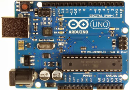
[ As usual, I'm not the first to think about this and there is even a complete interface for sale: the Keyrah V2. Better (or worse..) there is even an Etsy shop that has Commodore and many other computers converted to USB keyboards. But that's what I consider cheating. At least some hacking has to be done or it would be too easy ! My first thought was to use the Arduino Micro. While building my MAME cabinet I already discovered that this would have been the easiest way to implement a virtual USB keyboard.  On the biosrythm blog there is already a complete description on how to use Arduino to get the C64 keyboard to USB, but he is using the Duemilanove . ]

I picked up an empty C64 from ebay.de for €30 and bought a Arduino Pro Micro for only €7,- (who said hobbies have to be expensive?)

 The cable that sticks out on the right is the keyboard connector that used to be connected to the C64 motherboard.
First we obviously have to find out how the keyboard is actually wired. I found a neat diagram on the 'WaitingForFriday' blog:

Corrected C64 Keyboard matrix and keyboard connector diagrams  
Great, but it presents and unexpected surprise: we will need 16 Input / Outputs for reading this matrix. And the Micro Pro only has 9 digital I/O pins. My first idea was to expand the number of I/O pins by using some shift registers but then I remembered I also had some PICAXE chips in my toolbox. The PICAXE is a standard PIC micro-controller, pre-programmed with a Basic interpreter which makes programming real simple.And the PICAXE 28X2 has 16 freely configurable I/O pins so that should work fine.

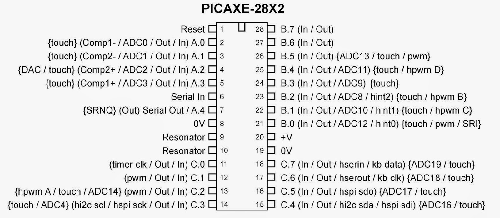
This chip even has all the I/O pins nicely laid out,making it easy to route the connector to the chip.
Some soldering will be necessary though to split out the connector in sections that will go to B0..B7
C0...C3 and C4...C7.
 Unfortunately this does not work. The PICAXE does not have any pull up or down resistors on its pins, so when no key is pressed they are all floating which results in random values.Adding a 10K pull up resistor to each input solves this problem immediately.
It's still a lot of puzzling to detect the right keys, certainly in combination with the  left-shift, right-shift or Commodore key but you can find a complete working version of the PICAXE software at the end of this page.
But since the PICAXE lacks an USB output we still need the  Arduino Pro Micro to create a keyboard compatible output.
So the whole exercise has been a fun and useful learning experience, but in hindsight it would have been easier to use the Arduino Leonardo... After all, this is a Pro Micro, but with plenty I/O to implement everything on a single board.


'Commodore 64 Keyboard Decoder. Columns (A..H) connected to Port B. Rows (1..8) to port C
'Both ports have 10K Pull up resistor on each pin


main:
symbol ROWS = b1
symbol COLUMNS = b2
symbol ROW = b4
symbol COLUMN = b5
symbol KEY =b6
symbol CHECK_ROW = b11
symbol CHECK_COL = b12
symbol TEMP_SUB = b13
symbol TEMP_SUB1= b14
symbol SPECIAL_KEY_PRESSED = b15
symbol RIGHT_SHIFT = b16
symbol LEFT_SHIFT = b17
symbol CTRL =b18
symbol PREVIOUS_KEY =b19
symbol KEY_COUNT=b20
symbol KEY_DELAY = b21

PREVIOUS_KEY = 0
KEY_DELAY = 100
do            ; Endless loop
 let dirsC = %11111111 ' switch all pins to outputs
 let dirsB = %00000000 ' switch all pins to inputs
 let pinsC = %00000000 ' switch all outputs low 
 b1 = pinsB 
 let dirsC = %00000000 ' switch all pins to inputs
 let dirsB = %11111111 ' switch all pins to outputs
 let pinsB = %00000000 ' switch all outputs low 
 b2 = pinsC
 
 b3 = NOT b1
 ROWS = NOT b2
 COLUMNS=b3

 'sertxd("B1,B2: ",#b1," ",#b2,13,10)
'Check if Left Shift is pressed 
 CHECK_ROW = %00001000
 CHECK_COL = %00000010 
 gosub CheckRowCol
LEFT_SHIFT = SPECIAL_KEY_PRESSED 
'Check if Right Shift is pressed
 CHECK_ROW = %00010000
 CHECK_COL = %01000000 
 gosub CheckRowCol
RIGHT_SHIFT = SPECIAL_KEY_PRESSED 
'Check if Right Shift is pressed
 CHECK_ROW = %00000100
 CHECK_COL = %00000001 
 gosub CheckRowCol
CTRL = SPECIAL_KEY_PRESSED   


 ROW = ncd ROWS
 COLUMN = ncd COLUMNS
 'sertxd("B1,B2,ROW,COL: ",#b1," ",#b2," ",#ROW," ",#COLUMN,13,10)
if ROW=0 or  COLUMN=0 then goto reset_keycount
 ROW = ROW-1
 COLUMN = COLUMN -1
 b0 = 8*COLUMN + ROW
 if LEFT_SHIFT =1 OR RIGHT_SHIFT=1 then goto Shift_pressed
 
  lookup b0,("1",8,"cr cq23wa~zse45rdxcft67ygvbhu89ijnmko0+pl,.:@-$*;/~=???",13,"?ffff"),KEY
 goto Key_Pressed
 Shift_pressed: 
       lookup b0,("!",8,"cr CQ",34,"#WA~ZSE$%RDXCFT&'YGVBHU()IJNMKO0+PL<>[@-$*]?~=???",13,"?ffff"),KEY
 Key_Pressed:
 'sertxd("KEY PRESSED!",#ROW," ",#COLUMN," ",#b0,":",b1,13,10)
 if KEY = "~" then goto continue     '~ marks an unprintable character (Only Shift is pressed)
 if KEY = PREVIOUS_KEY AND KEY_COUNT < KEY_DELAY then goto count_keys
 if KEY_COUNT <> KEY_DELAY then goto normal_delay
  KEY_DELAY = 3
      normal_delay:
 KEY_COUNT =0
 sertxd(KEY)
 serout A.0,T9600_8,(KEY)
 PREVIOUS_KEY = KEY
 goto continue


count_keys:
 KEY_COUNT = KEY_COUNT+1
 goto continue
reset_keycount:
 KEY_COUNT=0
 KEY=0
 PREVIOUS_KEY =0
 KEY_DELAY = 30
  
continue: 

loop   ; next loop

CheckRowCol:
SPECIAL_KEY_PRESSED = 0
 TEMP_SUB = ROWS and CHECK_ROW       'Check if a specific bit in ROWS is set
 if  TEMP_SUB = 0 then goto NotPressed
 TEMP_SUB = COLUMNS and CHECK_COL    'Check if a specific bit in COLUMNS is set
 if TEMP_SUB = 0 then goto NotPressed
 TEMP_SUB = NOB ROWS                    'Bit in ROWS and in COLUMNS found. Check how many bits in ROWS are set
 if TEMP_SUB = 1 then goto no_bit_reset 'If it is just one bit, do not reset it
 TEMP_SUB = NOT CHECK_ROW          'Invert all bits in the CHECK_ROW
 ROWS = ROWS and TEMP_SUB               'AND it with the ROWS to reset the bit we just found 
 no_bit_reset:
 TEMP_SUB = NOB b2
 if TEMP_SUB = 1 then goto no_bit_reset_2 
 TEMP_SUB= NOT CHECK_COL  
 COLUMNS = COLUMNS and TEMP_SUB 
 no_bit_reset_2:  
 SPECIAL_KEY_PRESSED = 1
NotPressed:
 
return

Friday, January 03, 2014

My Claim to MAME. (Building MAME: Intro)

This is the first post to what hopefully is going to be a (small) series. For many years I always had in the back of my mind that one day I wanted to build a MAME cabinet. It started back in the days when this was a rarity and only a few people did such a silly thing. Building it was complicated and expensive. Nowadays it looks like there are thousands of middle-aged men around the world that  attempt to re-capture their youth this way, and parts, plans and building instructions are widely available. Hundreds of on-line shops sell every possible part you'd ever need and even complete cabinets. (just Google for 'MAME Arcade Shop' and you 'll see what I mean)

But I want to keep the costs to a minimum by using parts I already have lying around.

The monitor

An old 15"LCD monitor that became surplus since everybody in my family now has it's own laptop...
The computer
 Any old laptop, even with a broken screen, will do. I've some of these lying around at the office.Or I could even use my Raspberry Pi.
The cabinet
 Some leftover MDF board is still in my shed for years. Maybe it's not enough for a full cabinet but it will get me started.
The controls
 I will need a joystick, some buttons, a 'spinner' (for playing Tempest) and a trackball. The trackball I already have. The joystick and buttons I had to buy, but they're not overly expensive ( €35,- for a joystick and seven buttons). The spinner is a bit of an issue. It seems not to hard to make myself, and they are quite expensive to buy so that will be a project in itself.
The controller
 To connect all the controls to the PC you need some kind of interface. Again this can be bought, but I have a feeling this probably can be done with one of the USB powered micro controller boards I have lying around like the NetDuino, Arduino or Launchpad.

Fortunately there are ton of sites (mainly blogs like these) with examples and how-to's. A few that I found very useful:
The Arcade Art Library - Where you can find all the graphics you need to create some good marquees and side art.
Project MAME- Some very good step by step instructions on how to build different types of cabinets. I did not use any of their design but there are some really useful hints and tips in there.
Build Your Own Arcade Controls (BYOAC) -  A general reference site with lots of info.
I Built An Arcade! - Great example of how to build a beautiful cabinet. Takes 13 months though...
How to build a bartop arcade - Another detailed how-to with some good ideas.
1UPArcade -  An amazing cabinet with a rotating control panel !

And finally:
What Is This Crap. - A showcase of how NOT to do it. (beware, contains strong language..)

The Games
By building a cabinet with a vertical monitor and just 4 buttons I have already limited the number of games that will be played on it. Which is fine with me since I prefer games from the seventies and eighties of which most were actually vertical platformers or shooters. Finding the games is easy, if you know where to look for. The best starting point I've found so far is the more than comprehensive MAME Database. This does not only list the games but has descriptions and screenshots. No downloads however since (as you may well know) games are usually still copyrighted and downloading ROMs is considered illegal. But once you know the name of the game you can just Google it to find the ROM. (don't be surprise if you find some more 'obscure' sites with ads that are not directly suitable for kids...)


Thursday, January 02, 2014

Buiding the Box (Building MAME: The Cabinet.)

When looking at all available designs and previously built MAME cabinets you soon find out that there is not just one universal design. And actually if you take a closer look at all the original cabinets you'll see they also differ a lot.
 I decided to take the 'Defender' design which is available as a Sketchup model. Imported it into the free 'DesignSpark' solid modeller and just projected the side of the box  on the piece of MDF I had available. This also gave me the chance to make it less deep. Since my cabinet will be fitted with a slim LCD screen instead of a bulky monitor it can be a lot smaller than the original. From the model I created the following plan-view of the side:
From there its just a matter of transferring the design to the board and use a jigsaw to shape them.
It's hard to saw straight lines using a jigsaw, so I first clamp on a piece of wood to align the saw. And when you just clamp two identical pieces of MDF together when you are sawing you get two perfectly identical sides.
Note that sawing two layers at the same time like this probably only works if you use 8 to 10 mm MDF. If you use it on thicker material it is very hard to keep the jigsaw exactly vertical and if it is slightly tilted your lower board will have a different size than the top one.

After I created the two sides I just estimated the optimum width by just holding the monitor next to one of the plates and finding good position. 50 cm seems like a good width so I just made the second MDF board exactly 50 cm wide. By doing this very carefully and making sure all corners of the board are now exactly 90 degrees it will be easy to create all front, top and rear surface plates.
And then we paint..and paint
and paint..and paint...
 Yes, two layers of MDF primer on each side is the minimum. Because MDF sucks... And that I mean literally. It just sucks up paint so for a good final finish you just have to primer it first.

Drilling the holes for the buttons. Using a 28 mm speed drill creates nice clean holes, but you must drill half way from one side, reverse the board and drill the rest from the other side.
Glue on the supporting blocks. I used a 20x20 wooden stick that I found in the shed. It's painted wood so using wood glue is not optimal since that is supposed to be applied to unpainted surfaces. Using a Polyurethane based construction adhesive is better.
In the mean time I keep refining the 3D model. And it's actually progressing faster than the real thing:

But after assembling the main parts it starts to look like real:
Next step would be to create the perspex cover for the control panel. I chose a standard 100x50 cm, 2mm thick perspex sheet which is available at almost every large hardware store. It was actually a coincidence that I chose 50 cm for the inner width of the cabinet but it's very convenient now since the perspex only has to be cut to length. And cutting perspex appeared a lot harder than I expected. First I tried to saw it using a fine pitch wood-saw intended for cutting laminate flooring. That does not work. The cut is very irregular and pieces just tend to break off. Second I tried cutting it using a hobby knife. This might be possible but its very hard to get one straight cut. Even if you use a steel ruler as a guide the knife just runs off if you are not very careful. After creating the cut (it's impossible to cut through the perspex) you can break it on the edge of a table. That does work but if the cut is pot too deep and not very straight you will get a very irregular edge with razor sharp points.
Finally used the blade  of a fine tooth hack-saw. That works better but it is essential that you carefully support both sides of the cut or the perspex will break.

Then the holes. This turned out to be even harder and it took me three attempts and a full panel of perspex before I finally had one that did not have cracks, or even completely destroyed edges. My tips for making holes:

Hole saw
- Use a vertical drill and push the drill very slowly. If you drill too fast the perspex will crack.
- Start every hole by drilling a small (3mm) hole in the centre. Then slowly increase the size of the drill but not more than 2 mm for every next step.
- Drill any hole larger than 10 mm using a hole-saw ! Trust me, any other drilling device (like a step-cone drill for example) will crack the perspex. This has one disadvantage. The arcade buttons require a 28 mm hole and this somehow seems to be a very uncommon size. So far I just found one set that has the 28 mm included.
- Support the perspex with wood and use a fresh piece for every hole so there is no hole in the wood under the perspex before you start the drilling.


CRACK !
 - Make sure you push down the perspex firmly and close to the drill. If you don't, the perspex might just jump up and crack.
- Don't drill too close to the edges. If there are holes near the edge of your control panel (like there are on mine) make the sheet larger, drill them first and then cut the sheet to size.


But finally with the inside painted deep-blue and the control panel covered with the perspex sheet it starts to look really good:
Creating the front bezel was actually very simple. First cut the perspex to size, place it in the cabinet and install the monitor so you can see were the screen is. Mark this on the perspex (I kept about 1 cm marging around the actual screen). Then (using a very sharp knife and a steel ruler) cut the protective foil and remove it on the edges. Then spray paint it a few times until the edges are really black. Make sure it really dry before removing the protective foil from the centre. And it looks really awesome when you look at it from the other side.

With the front-bezel installed, running LadyBug:
On the pedestal, with the top marquee installed:


Wednesday, January 01, 2014

It's all about Control. (Building MAME: The Controller)

Using the Arduino as a MAME interface.

MAME software runs on a computer. And modern computers do not have any simple I/O pins any more .(remember the parallel port that used to be on every computer for connecting a printer ?) So to connect switches and joysticks you will need some kind of interface that translates switch actions to USB. Early MAME builders cracked open standard keyboards and hard wired their switches to the different keys. This worked, but was quite difficult. Especially low cost keyboards did not have easy to solder contacts or convenient connectors to hook up to. Nowadays the most common solution is a dedicated controller that has lots of easy connectible inputs and USB output that just pretends to be standard keyboard. Best known are the UltiMarc I-Pac , OptiPac or J-Pac. An even lower cost solution are the Xin-Mo controller boards (aroun US$25,-, including the wires).
But to keep the cost to a minimum I intend to use what I already have...

The cheapest solution would be to use my FunDuino UNO R2 board. ( A cheap Chinese Arduino clone that ships at US$13,- from DealExtreme)
It's got 14 digital I/O pins so that should  be enough for an 8 way joystick + 7 buttons. (An 8 way joystick only has 4 switches). Since one of the buttons is just the 'Start' button so it will not need a fast response time I could also connect that to one of the analogue inputs and thus free 4 I/O pins for controlling additional stuff like lighting, sound or LEDs.
What I need is the Arduino to emulate a keyboard or to behave like a 'HID' (Human Interface Device). And if you know what to look for something like this is easy to find. Like on the blog of MitchTech. Now I did not immediately get the idea of this, until I realised that the Arduino board actually contains TWO different micro-controllers. One is the main controller (a ATmega328) that runs the Arduino 'sketches' and a second one (ATmega16u2) that just takes care of the USB communication from your PC to the main controller. And this communication controller is what we are re-programming to switch from a virtual COM port to a HID device.
First we will need a 'DFU' programmer. I use Windows, so I'll use 'FLIP' The procedure seems simple enough. Reset the Arduino, use FLIP to upload firmware. But I seem to have a problem with the reset. When I release the reset the board starts running the last sketch I've programmed it with, and it certainly does not show up as a new device. Which in turn is required so I can install the USB driver that FLIP needs. And of course I just overlooked something. When you have a non SMD Arduino board you should solder a resistor at the back. Yes, that is mentioned on the MitchTech page... (And it's no longer required with the latest revision of the Arduino UNO)
I just assumed I had a SMD board since there are many SMD components on the top of the board. But it's probably only so if the processor itself is a SMD version.
And indeed, when the resistor is mounted and we short circuit the two pins, left-top of the board, the unit shows up in the Windows device manager as a 'DFU' device. Left click on it, select 'Update Driver' and select the driver from the FLIP->usb directory. Then it shows up as an A90USB8. And when we unplug it and plug it back in it is again visible as the virtual serial port. 

Now we need to know what codes should be sent when a button is pressed. Which keys do we need to play MAME games ?
The full overview is on this page. And this is the selection of the ones I think I'll need:
Key                  Function               HID Key  
5                    Insert coin            34
1, 2                 Start (players 1, 2)   30,31
Arrow keys (U,D,L,R) Move Joystick          82,81,80,79
Left Control         Button 1               Bit0
Left Alt             Button 2               Bit2
Space                Button 3               44
Left Shift           Button 4               Bit1
Z                    Button 5               29  
X                    Button 6               27
ESC (Escape)         Quits the game         41

('Bit0..Bit2' marks a bit in the Modifier byte)

First I just used the MitchTech sample program. This just detects what pin is activated, sends a single key and then after 100 mS a 'releasekey' command. So if you press and hold a button you are sending 10 keydown / key-release commands per second. This works, but not very good. Most MAME games do not respond very well to a constant stream of key-presses. The movements often get a bit jerky, probably due to a regular key-buffer overload. Also it just sends one key at a time while the keyboard code does allow for multiple keys.
In my program I created a loop that checks every time which contacts are closed, find the keyboard code that has to be generated for that contact and add that to the keyboard message. Then only send the message itself when its different from the previous one. And when a key is released its code is forced to 0 so a key-release is only sent once. Also I use some analog inputs as extra inputs for buttons by just reading the voltage on that input. Note that these inputs are 'floating' so if they are left open the result may be unpredictable. You will need to add pull up or down resistors to the inputs.

So in the end the program looks a lot different but does exactly what I need:

MAME.ino (on my Google Drive)

Now what I love about software: you can re-configure the buttons and joystick at no cost after you wired them...
 I know most people use wires with crimp-on connectors for wiring their controls, but I just love soldering and for me this is much faster too. So I soldered all connections to the joystick and the plug on the FunDuino board. Here the buttons are not connected yet, but the black wire will serve as common ground for these.
Testing is a little hard since most normal software does not really show you if you pressed a Control or Shift key. But the 'GhostKey' program is an extremely simple way to test what code your keyboard is sending.
While testing this set-up with the actual buttons I noticed another problem. How do you insert a 'coin' to get the game started when you don't have an actual coin-slot ?  
I decided to make the 'Single player - start game' button to double as a coin insert. That's the benefit of having a programmable controller. Now it just checks the state of the 'start game' button and if it's pressed for more than 2 seconds it sends key '5' (Insert Coin) . But if you release it sooner it just sends '1' (Single player start).

Wiring it was pretty easy. As shown on the right I screwed the Arduino to the bottom and glued a small breadboard next to it. This way it is fully reconfigurable and I can just add some pull-up resistors if needed. The only thing that worries me a bit is that the breadboard is upside-down and the wires could fall out, but that has not happened yet. And when everything works fine I can make a more permanent solution.


(Note: If you start out without a board and want to buy one it is probably better to choose the Arduino Micro since that has 20 I/O pins and  'mouse' and 'Keyboard' commands built in)

Ctrl Alt and....CRASH..
After a while I noticed that the system sometimes seems to crash while playing games that use both the A and B button. Some further investigation showed that it actually happened when pressing the buttons AND moving the joystick Left or Up. What actually happens is that you create the key combination Ctrl Shift and Left arrow, which is caught by the Intel graphics driver. So it just rotates the screen, or changes the resolution and (worse) throws you back to the main window. The solution was simple. Left click on the desktop, select 'Graphic options' and in the Intel graphics settings just disable hotkey support.